
November 2, 2026
The real job of structural design software is consistency, not calculation

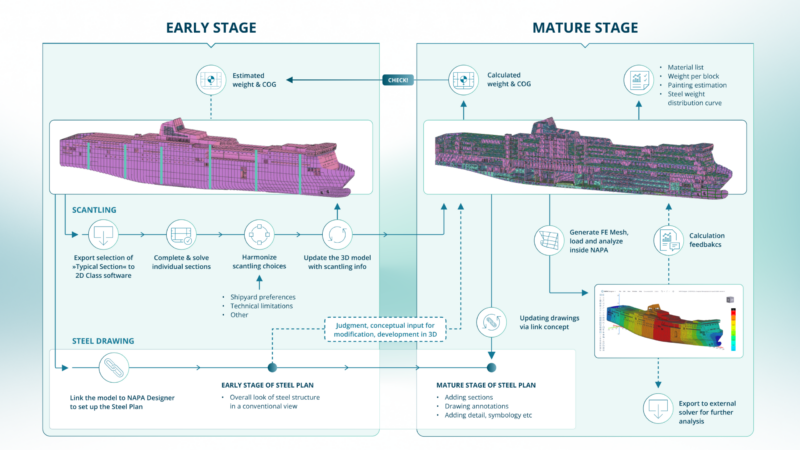
Turn off the steel layer on a ship’s CAD drawing, and everything else – the cabins, the equipment, the tanks – suddenly looks like it’s floating in empty space. The structure isn’t a secondary output of ship design. It’s what the rest of the ship design hangs off of.
But structural design rarely gets treated with that weight. It’s often reduced to “the strength calculation,” a single check that happens somewhere in the middle of the process. In practice, it’s the coordinated work of multiple specialist teams producing weight estimates, bills of materials, 2D drawings, classification submissions, and finite element models, all of which are supposed to describe the same ship. The real difficulty isn’t any one of these tasks. It’s keeping all of them consistent with each other as the design evolves.
Take something as simple as a 6 mm steel plate on a bulkhead. That one plate has a weight, a cost, a required paint area, a shape that needs to appear correctly on a drawing, and a strength that needs to be verified against multiple loads. Ideally, its thickness is defined in exactly one place, and everything else – the drawing, the weight calculation, the material order – follows from that single definition. In practice, that’s hard to achieve, and the gap between “should be consistent” and “is consistent” is where shipyards lose time.
Two points where consistency typically breaks
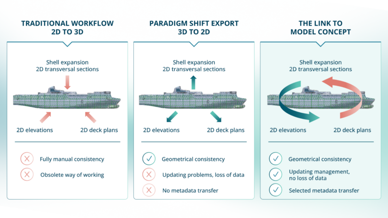
Between the 3D model and the 2D drawing. Under time pressure, it’s common for designers to unlink steel drawings from the 3D model and finish them independently. Every later change then has to be re-entered by hand into each affected drawing, and that manual reconciliation is where mistakes creep in, especially when a project is picked back up after sitting idle for weeks or months.
Between the structural model and the FE analysis model. Finite element analysis is mandatory, both for classification and for the designer’s own confidence in the design. But the moment a mesh is exported from the 3D model into an external FE preprocessor, the two models stop being the same thing. They keep evolving in parallel, disconnected, and someone has to decide when it’s worth re-exporting and starting the fix-up work over again.
Closing both gaps
NAPA Drafting closes the first gap by physically linking every 2D drawing to the 3D model it represents. The line styles, the scantling annotations, the thickness callouts – all of it comes directly from the 3D model’s data. Change the model, and the drawing reflects it automatically, ready for the designer to review and accept rather than redraw.
NAPA FEM closes the second gap by generating, constraining, loading, and solving the finite element model inside the same environment as the structural design itself, rather than handing a mesh off to a separate tool. A full hull girder FE model for a medium-sized ferry, something in the range of 255,000 shell elements, can now be generated directly from the NAPA Steel model in about 20 minutes.
Putting it to the test: a hull girder analysis
To check whether this actually produces usable results, and not just a mesh that happens to solve, a full hull girder global strength analysis was built entirely from data already sitting in NAPA’s Loading Condition task: floating position, tank and cargo loads, steel weight distribution, and the rest of the lightweight items. Using C# scripting, that data was converted directly into nodal forces, pressures, and constraints on the FE model, producing a self balanced global load case.
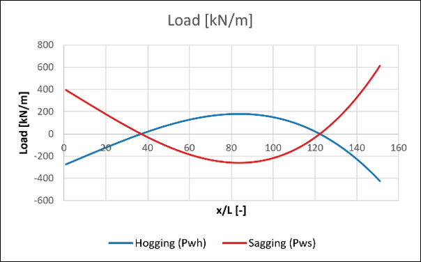
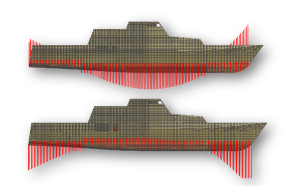
The results were then checked against the same loading condition’s shear and bending moment curves, and the comparisons, generated automatically as Excel output, held up well both graphically and numerically.
What this does, and doesn’t, change
None of this removes the need for specialist engineering judgment, independent verification, or external solvers when a particular analysis calls for them. What it does remove is the duplicated setup work and manual reconciliation that, in practice, decide whether a structural workflow actually holds together or quietly falls out of sync, one drawing and one exported mesh at a time.
This post is based on a paper presented at COMPIT (Computer and IT Applications in the Maritime Industries) by Francesco Oneto of NAPA.